1.1. Static data
The static data describe the topology of the network and the initial power-flow solution from which the dynamic models are initialised. This covers buses, lines, transformers, switches, and shunts. The initial operating point is specified by voltage magnitude and phase angle at each bus via LFRESV records.
1.1.1. Data used by RAMSES
- BUS name vnom pload qload bshunt qshunt ;
Defines a bus in the network.
- Parameters
name (str) – (max 8 characters) name of the bus
vnom (float) – base voltage, in kV. Used to convert line and transformer parameters to per unit.
pload (float) – active power load, in MW (ignored by RAMSES; used by PFC only)
qload (float) – reactive power load, in Mvar (ignored by RAMSES; used by PFC only)
bshunt (float) – nominal reactive power, in Mvar, of constant-admittance shunt compensation (positive = capacitor, negative = inductor). Ignored by RAMSES.
qshunt (float) – nominal reactive power, in Mvar, of constant-power shunt compensation. Ignored by RAMSES.
Note
Only
nameandvnomare used by RAMSES. All other fields are read by the PFC module only.
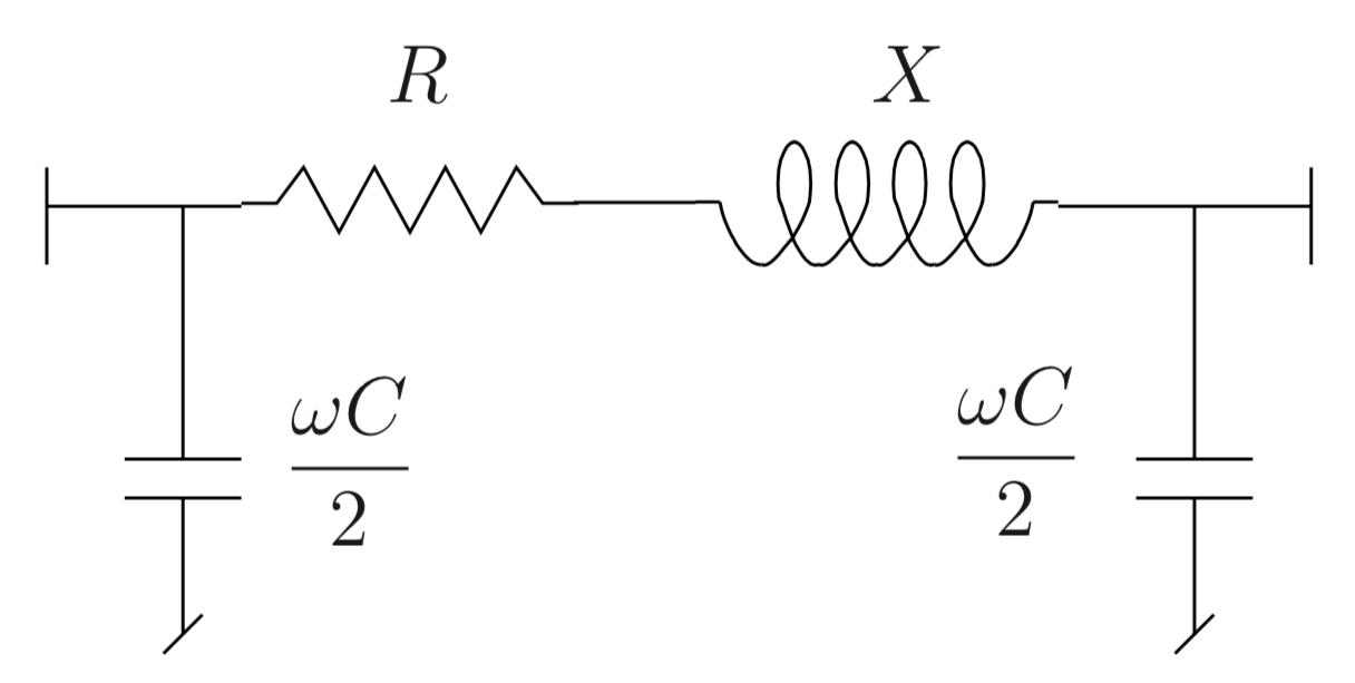
- LINE name from to R X WC2 SNOM BR ;
Describes a transmission line, cable, or series capacitor.
- Parameters
name (str) – (max 20 characters) name of the line
from (str) – (max 8 characters) name of the “from” bus (orientation is arbitrary)
to (str) – (max 8 characters) name of the “to” bus
R (float) – resistance, in Ω
X (float) – reactance, in Ω
WC2 (float) – half shunt susceptance \(\omega C/2\), in μS
SNOM (float) – nominal apparent power, in MVA. Set to zero to indicate no limit.
BR (int) – breaker status. 0 = both ends open; any other value = both ends closed.
- SWITCH name from to BR ;
Describes an ideal switch (zero-impedance connection) between two buses.
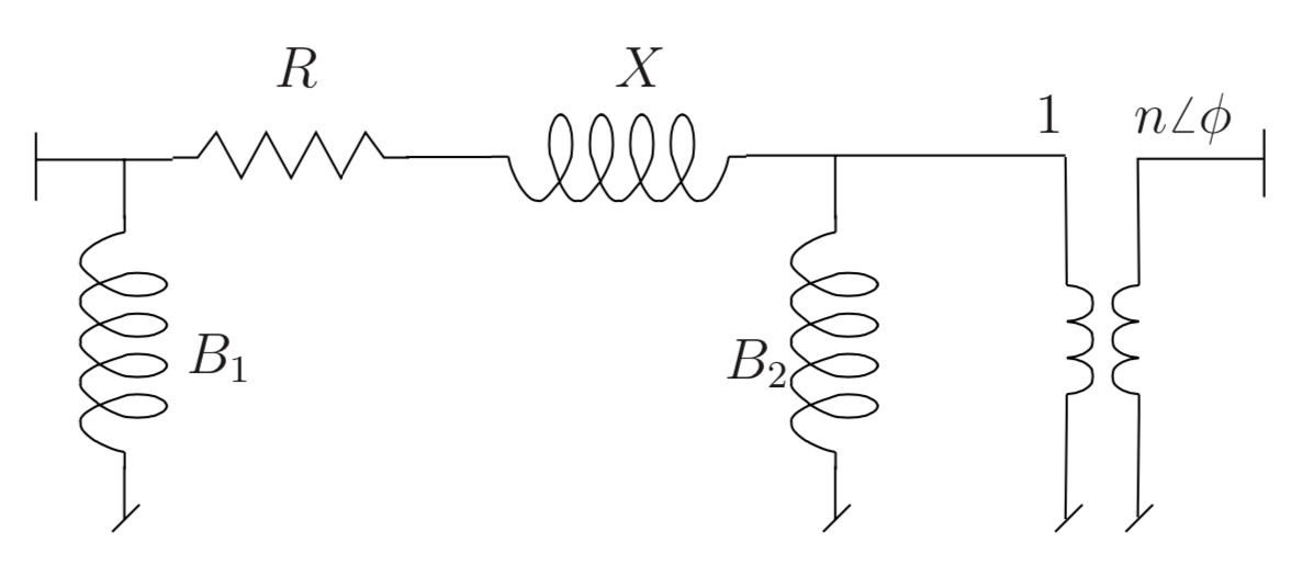
- TRANSFO name from to R X B1 B2 N PHI SNOM BR ;
Transformer record (full model with ratio and phase shift).
- Parameters
name (str) – (max 20 characters) name of the transformer
from (str) – (max 8 characters) name of the bus on the “1” side of the ideal transformer
to (str) – (max 8 characters) name of the bus on the “n” side of the ideal transformer
R (float) – resistance, in % on the (VB1, SNOM) base
X (float) – reactance, in % on the (VB1, SNOM) base
B1 (float) – magnetising susceptance on bus 1 side, in % on the (VB1, SNOM) base (usually negative)
B2 (float) – magnetising susceptance on bus 2 side, in % on the (VB1, SNOM) base (may be zero)
N (float) – off-nominal turns ratio n, in % on the (VB1, VB2) base
phi (float) – phase angle shift φ, in degrees
SNOM (float) – nominal apparent power, in MVA. Must not be zero.
BR (int) – breaker status. 0 = both ends open; any other value = both ends closed.
- TRFO name from to con R X B N SNOM NFIRST NLAST NBPOS TOLV VDES BR ;
Simplified transformer record (
B2 = 0,φ = 0). Tap-changer parameters are used by PFC only; RAMSES treats it as a fixed transformer.- Parameters
name (str) – (max 20 characters) name of the transformer
from (str) – (max 8 characters) “1” side bus
to (str) – (max 8 characters) “n” side bus
con (str) – controlled bus name (must be one of the two terminals). Use blank to fix the ratio.
R (float) – resistance, in % on the (VB1, SNOM) base
X (float) – reactance, in % on the (VB1, SNOM) base
B (float) – magnetising susceptance, in % on the (VB1, SNOM) base
N (float) – off-nominal turns ratio, in %
SNOM (float) – nominal apparent power, in MVA. Must not be zero.
NFIRST (float) – ratio n at the first tap position, in % (PFC only)
NLAST (float) – ratio n at the last tap position, in % (PFC only)
NBPOS (float) – number of tap positions (PFC only)
TOLV (float) – voltage control half-deadband, in pu (PFC only)
VDES (float) – voltage setpoint at the controlled bus, in pu (PFC only)
BR (int) – breaker status. 0 = open; any other value = closed.
Note
NFIRST,NLAST,NBPOS,TOLV, andVDESare ignored by RAMSES. Dynamic tap-changer behaviour must be implemented as a discrete controller (DCTL) in the dynamic data.
- NRTP name from to G11 B11 G12 B12 G21 B21 G22 B22 BR ;
Non-reciprocal two-port network element (asymmetric π-model). Used to model devices where the admittance matrix is non-symmetric.
- Parameters
name (str) – (max 20 characters) name of the element
from (str) – (max 8 characters) “from” bus
to (str) – (max 8 characters) “to” bus
G11 (float) – real part of \(Y_{11}\), in pu on system base
B11 (float) – imaginary part of \(Y_{11}\), in pu
G12 (float) – real part of \(Y_{12}\), in pu
B12 (float) – imaginary part of \(Y_{12}\), in pu
G21 (float) – real part of \(Y_{21}\), in pu
B21 (float) – imaginary part of \(Y_{21}\), in pu
G22 (float) – real part of \(Y_{22}\), in pu
B22 (float) – imaginary part of \(Y_{22}\), in pu
BR (int) – breaker status. 0 = open; any other value = closed.
- SHUNT name bus QNOM BR ;
Fixed shunt element connected to a bus.
- LFRESV name mag phase ;
Specifies the initial bus voltage from the power-flow solution.
- Parameters
These records are typically produced by the PFC module and loaded as part of the static data.
1.1.2. Data used by PFC only (ignored by RAMSES)
The following records are read by the power-flow module (PFC) to compute the initial operating point. RAMSES ignores them.
- GENER name bus mon p q vimp snom qmin qmax br ;
Generator specification for load-flow computation.
- Parameters
name (str) – (max 10 characters) name of the generator
bus (str) – (max 8 characters) connection bus
mon (str) – monitored bus (set to
CON BUSif unused)p (float) – scheduled active power production, in MW
q (float) – reactive power production or initial value, in Mvar
vimp (float) – imposed terminal voltage, in pu. Zero = PQ bus; non-zero = PV bus (Q is then ignored).
snom (float) – nominal apparent power, in MVA. Required when modelling the generator dynamically.
qmin (float) – lower reactive power limit, in Mvar
qmax (float) – upper reactive power limit, in Mvar
br (int) – breaker status. 0 = open; any other value = closed.